
Update 17th January 2020: new version 1.3!
After a few versions of the Compustar firmware that I used as a way to better understand the intricacies of the Compustar firmware, I was ready for the major task of adding enough support to implement a full ASCOM driver to connect the Compustar to a modern PC with a standard astronomy software.
I knew I had to develop two different but at the same time complementary pieces of software: one running on the PC, and one running on the Compustar.
The PC part was going to be more complex, given that the PC is much more powerful than the Compustar, but at the same time it was easier to develop because I could use a modern, high level language, .NET. The Compustar part had to be much smaller, but at the same time it was harder to develop, because it had to be written in assembly language with a very limited amount of resources.
PC-Compustar cable connection
The connection between the Compustar and the PC is done via a standard RS232 port or using some kind of USB<>RS232 dongle as modern PCs no longer have serial ports. In case you need an USB<>RS232 dongle, be sure to use one with true RS232 drivers: they normally come with DB9 male connectors. TTL output dongles (like the ones used with breadboards and/or Arduino) don’t work (and may damage your PC).
You then need a special cable, because even if the Compustar has a mating DB9 female connector, its pinout is not standard, since the Compustar predates the use of DB9 connectors as serial ports (they used DB25 back then) and therefore it’s not going to work if connected directly (and may also damage your Compustar!).
This special cable has the following connections:
| DB9-F (PC side) | DB9-M (Compustar side) | Pin function |
|---|---|---|
| Pin 2 | Pin 2 | Data line, Compustar to PC |
| Pin 3 | Pin 3 | Data line, PC to Compustar |
| Pin 4 | Pin 4 | PC Mode enable (DTR on PC) |
| Pin 5 | Pin 1 | Ground |
All other pins must be left unconnected (especially PIN 8, Compustar side).
This cable should be connected between the PC and the Compustar, using the leftmost DB9 connector on the Compustar itself.
Compustar configuration
To use the ASCOM driver on the Compustar you must install the 64K version of the Compustar firmware, revision 1.70 or higher. 32K versions don’t contain the required protocol support and therefore cannot be used. These new firmwares can be found here.
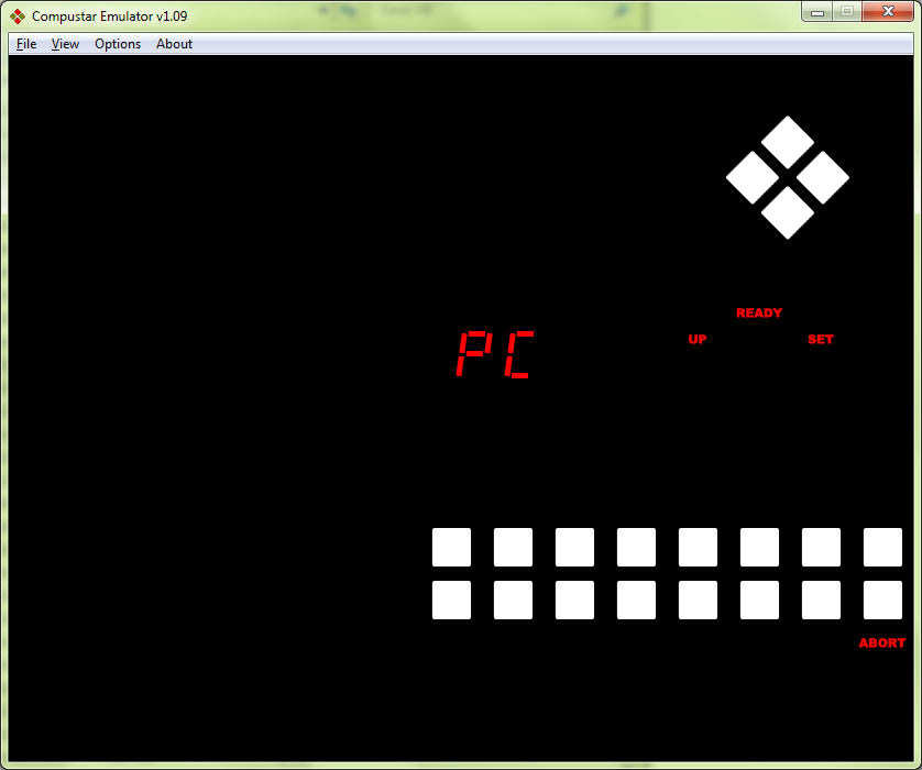
The Compustar in PC mode
The ASCOM protocol support is not always enabled in the Compustar: there is an option (OPT-6) to do so. This is done because it uses parts of the serial port circuitry the original firmware never used, and therefore there is a small possibility that this circuitry does not work as it should.
To enable option 6, press OPT and then the key ‘6’. The option is enabled if the ‘6’ label is flashing, it is disabled if the ‘6’ label isn’t flashing.
You should enable this option (at least the first time) without having connected the PC. Upon enabling OPT-6, nothing should happen. If, on the other hand, the Compustar immediately switches to PC mode (clears all the digits and displays “PC”) it means that the RS232 circuitry is not working as it should. In this case, press ABORT which will immediately disable OPT-6 and PC mode will terminate. If this happened, either you didn’t do THIS modification or the Compustar has an hardware problem that should be fixed.
ASCOM driver installation
Driver installation is done with few simple steps:
First, you have to download and install the ASCOM platform (if you haven’t installed it yet).
Current version (October 2019) is 6.4SP1, and it can be found on ASCOM web site http://www.ascom-standards.org/. You’ll find a download button on the right part of the screen.
Second, you have to download and then install the actual Compustar driver from here:

Then, run your favorite software, choose to use an ASCOM telescope, in the ASCOM Telescope Chooser select “Compustar Telescope” and click the “Properties…” button to configure the Compustar driver.
You will see a dialog box like this:
 Here you can configure a few things. The Serial port is the serial port you have connected the Compustar to. If you don’t know which one to use, just try one at the time. If you pick the wrong one the software will not connect (though it may or may not show an error). You may enable Show errors on connection to have a message box explaining connection errors (though this may violate the ASCOM guidelines).
You may also choose to program the Date/Time from the PC to the Compustar upon connect, select the guide speed (used for the PulseGuide ASCOM method), and choose to display the RA/DEC coordinates on the Compustar display (otherwise the display will not display anything). To reduce the load on the Compustar, this new 1.3 version will by default caches some requests so these will not be done too frequently. “Cache Life” controls how long a cached value will be considered valid before requesting it again (default value is 0.25s).
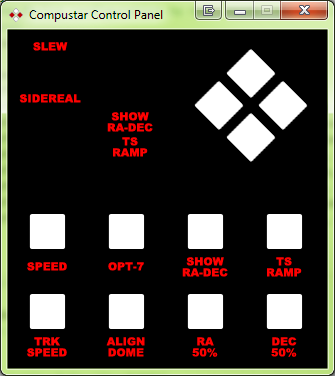
By selecting “Show telescope Panel” (a new option in version 1.3), a small Compustar-like control panel will be shown when the telescope is first connected.
Using this panel you can move the telescope, change the manual movement speed (SPEED), the tracking speed (TRK SPEED), interact with the dome (via OPT-7 and ALIGN DOME), reduce the slewing speed to 50% (either in RA, DEC or both), select a different acceleration ramp for slews (TS RAMP). If you check “Show Dome options” too, OPT-8-2 and OPT-8-3 (dome-related options) will be shown, together with two additional buttons to toggle them.
Note that this control panel requires version 1.90 (or greater, 64K) of the Compustar firmware. Previous releases will still work, but the Compustar Control Panel will not be shown with them, even if the “Show Telescope Panel” item is checked.
Compustar protocol
If you want to drive the Compustar directly without using our ASCOM driver, this is the the low level protocol documentation.
This new firmware has two working modes:
“USER” mode, which is actually the original Compustar mode, where the user has full control of the telescope and the protocol on the serial port is the original Compustar protocol (though some memory location changed, and therefore old software using this protocol may no longer work).
“PC” mode, where the computer takes control of the Compustar and the user can only change the speed between SET and SLEW, move the telescope around with the movement buttons and abort slews.
The selection between the two modes is done using the DTR signal on the serial port: when the DTR signal is low (nominal -12V), the Compustar is in “user” mode, when it is high (nominal +12V) the Compustar will be in “PC” mode. With the modification detailed here, when no cable is connected to the RS232 port of the Compustar the Compustar itself will be in “USER” mode.
The connection procedure is:
- Raise the DTR signal
- After approximately 100ms the Compustar will reply with “PCx.xx” where x.xx is the firmware revision. So, with firmware 1.70, the replied bytes will be <0x50 0x43 0x31 0x2E 0x37 0x30>
- You should have set a timeout (let’s say, 1 second) to tell the user that the connection wasn’t established if you didn’t receive these bytes. If the timeout occurs, lower the DTR signal and return an error.
To disconnect, simply lower the DTR signal. The Compustar will return to “USER” mode.
If you got the reply as expected, you can start sending commands to the Compustar, following these guidelines:
- Everytime you send a byte to the Compustar (be it either a command or a parameter) you MUST wait for the Compustar to echo the byte back. You may NEVER send more than one byte at the time. The echoed byte will be the byte you sent (therefore you can avoid checking its value) except for the first byte (0x27) which may be echoed back as 0xFF in the case the Compustar has exited “PC” mode (and in this case you should disconnect from the Compustar and optionally notify the user).
- Always setup a timeout (1 second is normally more than enough) to return control to the calling program/notify the user in case the communication is interrupted for some reason (the serial port cable was unplugged, the Compustar powered off…)
Command execution:
- Send 0x27
- Wait for echo. If a timeout occurs or the echo is not 0x27, disconnect from the Compustar and abort command execution.
- Send the command byte (see table, below) (and wait for echo)
- Send command parameters (if any) one byte at the time waiting for each one to be echoed back.
- Wait for the Compustar response or the timeout to occur. The response could be: “PC” (0x50 0x43) if the command was recognized or “PE” (0x50 0x45) if it’s an unknown command.
- In case of timeout or unknown command act accordingly
- In case of command executed ok (“PC”), read and process all the response bytes (see table, below)
| Command | Operation | Parameters | Response | Format and examples |
|---|---|---|---|---|
| 0x00 | Get RA | 0 bytes | 3 bytes | If divided by 3200 gives RA in minutes. <6E B8 3F> → 0x3FB86E → 4175982 → 1304.994375 min → 21h44.9' |
| 0x01 | Get Declination | 0 bytes | 3+1 bytes | /128 gives the declination in primes. <DB 2A 01 00> → 0x012ADB+0x00 → 76507 → 597.7109375' → 9°58'; <00 8C 0A 01> → 0xA8C00+0x01 → 691200 → -90°00' |
| 0x02 | Get Site Longitude | 0 bytes | 2 bytes | In primes. <49 52> → 0x5249 → 21065' → 351°5' |
| 0x03 | Get Site Latitude | 0 bytes | 2+1 bytes | In primes. <B0 0A 00> → 0x0AB0+0x00 → 2736' → 45°36'.<B0 0A 01> is -45° 36' |
| 0x04 | Get Date/Time | 0 bytes | 6 bytes | First 3 bytes are the time, in 0.1s, since 00:00:00 (UT). Last 3 bytes are Year (since 1900), Month and Day. <D3 13 06 75 08 1D> → 11:03:49.0, 29 August 2017 |
| 0x80 | Set Site Longitude | 2 bytes | 0 bytes | In primes. <27 80 49 52> locates the viewing site at 351° 5'. |
| 0x81 | Set Site Latitude | 2+1 bytes | 0 bytes | In primes. Last byte is the sign: <27 81 B0 0A 00> → +45°36'; <27 81 B0 0A 01> → -45°36'. |
| 0x82 | Set Time | 7 bytes | 0 bytes | 7 bytes from 0 to 9 (binary), in order: sSmMhHd (s=seconds, S=10-seconds, m=minutes, M=10-minutes, h=hours, H=10-hours, d=tenth of a second). <27 82 06 04 08 01 03 02 07> sets the time to 23:18:46.7 (UT) |
| 0x83 | Set Date | 6 bytes | 0 bytes | Set date and clear the time to 00:00:00.0. 6 bytes from 0 to 9 (binary) in order: dDmMyY (d=day, D=10-day, m=month, M=10-month, y=year, Y=10-year). Year starts from 2000, month and day from 1. <27 83 09 02 08 00 07 01> sets the date to 29 August 2017. |
| 0x84 | Show RA/DEC | 1 byte | 0 bytes | If the parameter is 0x00, the Compustar display will be blank, otherwise telescope RA and Declination will be shown. |
| 0x85 | Slew to coordinates | 7 bytes | 1 byte | Slew to given coordinates (JNow). <RA RA RA DEC DEC DEC DEC> RA and DEC are in the same format as the Get RA and Get DEC commands, with the difference that the DEC sign byte is actually: Bit 0=sign, Bit 1=Apply atmospheric refraction (1=yes), Bit 2=Do altitude check (1=yes). Return value will be 0x00 if the slew started, 0x01 if the object was TOO LOW (only with altitude check), 0x02 if the telescope was parked. |
| 0x86 | Sync to coordinates | 7 bytes | 0 bytes | Sync to given coordinates (JNow). <RA RA RA DEC DEC DEC DEC> RA and DEC are in the same format as the Get RA and Get DEC commands. |
| 0x87 | Nop | 0 bytes | 0 bytes | No operation |
| 0x88 | Park | 0 bytes | 1 byte | Park the telescope (calls the END procedure). Return value is 0x00 if the park is possible, something else if the telescope is already parked. |
| 0x89 | Unpark | 0 bytes | 1 byte | Unpark the telescope. Return value is 0x00 if the telescope has been unparked, 0x01 if the telescope is not currently parked. |
| 0x8A | Get status | 0 bytes | 1 byte | Returned value: Bit 0: Slewing in RA Bit 1: Slewing in DEC Bit 2: Parking (slewing for parking) Bit 3: Parked Bit 4: Tracking Bit 5: IsSlewing Bit 6: RA PulseGuiding Bit 7: DEC PulseGuiding |
| 0x8B | Set tracking | 1 byte | 0 bytes | 0x00 stops tracking, 0x01 enables tracking. Note: tracking can be disabled only in PC mode. It will restart if PC mode is exited. |
| 0x8C | Set guide speed | 1 byte | 0 bytes | Set Pulseguide speed from 0x01 (1/256 X) to 0xFF (255/256 = 0.99X). 128 is 0.5X. |
| 0x8D | Pulse guide E | 1 byte | 0 bytes | Pulse guide East. Parameter is pulse length, in ticks. |
| 0x8E | Pulse guide W | 1 byte | 0 bytes | Pulse guide West. Parameter is pulse length, in ticks. |
| 0x8F | Pulse guide N | 1 byte | 0 bytes | Pulse guide North. Parameter is pulse length, in ticks. |
| 0x90 | Pulse guide S | 1 byte | 0 bytes | Pulse guide South. Parameter is pulse length, in ticks. |
| 0x91 | Get All informations | 0 bytes | 8 bytes | Same as "Get RA" followed by "Get DEC" followed by "Get status" |
| 0x92 | Get Options | 0 bytes | 4 bytes | FW 1.90+. Returned bytes are: Options, Options 8, Options 9, 0x00. Last byte is a placeholder for a future new option byte |
| 0x93 | Set Option | 1 byte | 0 bytes | FW 1.90+. Parameter: Bits 7..6: 00 = Clear, 01 = Set, 10 = Toggle, 11 = NOP; Bits 5..4: 00 = Options, 01 = Options 8, 10 = Options 9; Bit 3: 1 = Save to NVRAM; Bits 2..0: Option to clear/set/toggle |
| 0x94 | Get TrackingRate | 0 bytes | 1 byte | FW 1.90+. Returns the current tracking rate: 0 = Sidereal, 1 = Lunar, 2 = Solar |
| 0x95 | Set TrackingRate | 1 byte | 0 bytes | FW 1.90+. Parameter is the new tracking rate: 0 = Sidereal, 1 = Lunar, 2 = Solar. This new tracking rate will NOT be saved to NVRAM |
| 0x96 | Get Status 2 | 0 bytes | 1 byte | FW 1.90+. Returned value: Bit 0: Current speed (0=SET, 1=SLEW) Bit 1: "SideOfPier" (Set to 1 when a movement went through the NCP/SCP) Bit 2: Unused Bit 3: Unused Bit 4: Unused Bit 5: Unused Bit 6: Unused Bit 7: Unused |
| 0x97 | Change Speed | 1 byte | 1 byte | FW 1.90+. Change speed: 0x00=SET, 0x01=SLEW, 0x02 Toggles current value. Returns the same byte as the "Get Status 2" (0x96) command. |
| 0x98 | ManualMove OFF | 0 bytes | 0 bytes | FW 1.90+. NSEW keys emulation: no key pressed. |
| 0x99 | ManualMove EAST | 0 bytes | 0 bytes | FW 1.90+. NSEW keys emulation: East (Left key) |
| 0x9A | ManualMove WEST | 0 bytes | 0 bytes | FW 1.90+. NSEW keys emulation: West (Right key) |
| 0x9B | ManualMove SOUTH | 0 bytes | 0 bytes | FW 1.90+. NSEW keys emulation: South (Down key) |
| 0x9C | ManualMove SOUTH + EAST | 0 bytes | 0 bytes | FW 1.90+. NSEW keys emulation: South and East (Down and Left keys) |
| 0x9D | ManualMove SOUTH + WEST | 0 bytes | 0 bytes | FW 1.90+. NSEW keys emulation: South and West (Down and Right keys) |
| 0x9E | ManualMove NORTH | 0 bytes | 0 bytes | FW 1.90+. NSEW keys emulation: North (Up key) |
| 0x9F | ManualMove NORTH + EAST | 0 bytes | 0 bytes | FW 1.90+. NSEW keys emulation: North and East (Up and Left keys) |
| 0xA0 | ManualMove NORTH + WEST | 0 bytes | 0 bytes | FW 1.90+. NSEW keys emulation: North and West (Up and Right keys) |
| 0xA1 | Force DOME Align | 0 bytes | 0 bytes | FW 1.90+. Same as SLEW/ALIGN: force the DOME to be aligned with the telescope |
Notes:
- Parameter is the number of bytes to send as a parameter for a given command
- Response bytes is the number of bytes to read after having received the “PC” response
- When either number has a +1, the last byte will be the sign of the parameter/response: 0x00→Positive, 0x01→Negative, except when noted (in the “Slew To Coord” command, for example)
- Timings are in “ticks”. Each tick is 18.7245714 ms (131072/7000) long
- Since the communication buffer is too small to hold both the date AND the time, there is no “Set Time and Date” command. You should use the “Set Date” command first (which sets the date but ALSO sets the time to 00:00:00.0 to avoid date rollovers) and THEN use the “Set Time” command to adjust the clock.
- Command 0x91 (Get All informations) was already present in firmware 1.80. I simply forgot to document it here.