In this post I’m describing all the hardware modification that can be done to the Celestron Compustar to improve or enhance its operation. The first of these modifications was previously posted in the “New Compustar Firmware” post, but it has been now moved here.
A non volatile memory AND real time clock for the Compustar
You can add a non volatile memory/real time clock chip to the Compustar.
This chip will allow you:
- to save what you have configured (options, location) and keep them configured even when you power the Compustar off,
- to set the clock once (using either BEGIN or SET/TIMEDATE) and have it already set.
The required IC (Maxim/Dallas DS1643) can be bought on EBAY or AliExpress. Regular IC resellers like DigiKey or Farnell seem unfortunately to have discontinued this IC. There could be other options but this is the only one (that I know of) that can be directly installed in the Compustar without other modifications.
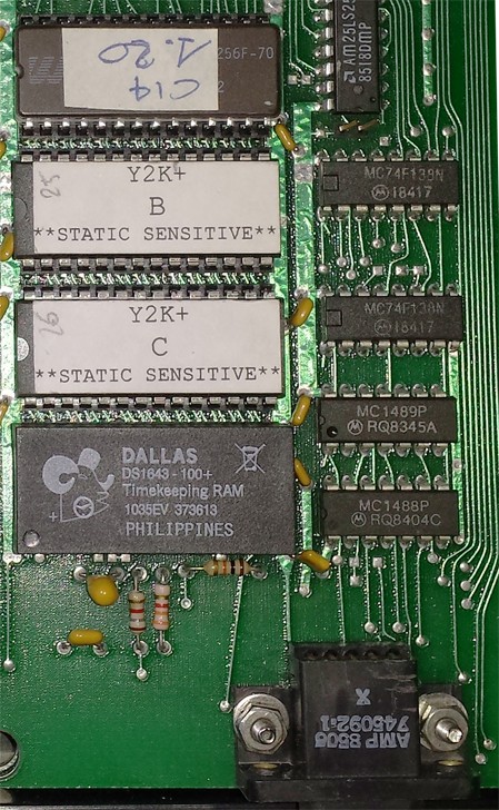
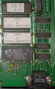
The empty socket where you can install the DS1643 chip
The DS1643 chip installed. The small dip indicating pin 1 of the DS1643 must be oriented like the other EPROM chips.
Installation is very easy. It’s enough to insert the DS1643 IC into the unused socket, taking care that the small dip indicating pin 1 is oriented towards the bottom side of the board.
64kBytes firmwares
While the original Compustar code EPROM is 32Kbytes (27C256), the hardware was designed to handle 64KBytes EPROMs too (27C512). Probably late in the Compustar firmware design 32KByte were deemed enough and therefore the full 64KBytes support was left out, probably just for convenience.
Therefore a couple modifications are required to install 64KBytes EPROMs.
First of all, there is a small PCB trace to cut on the top side of the microprocessor board. Use an Exacto knife or any other sharp object.
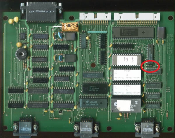
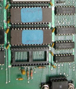
Location of the jumper/PCB trace to cut (click to enlarge)
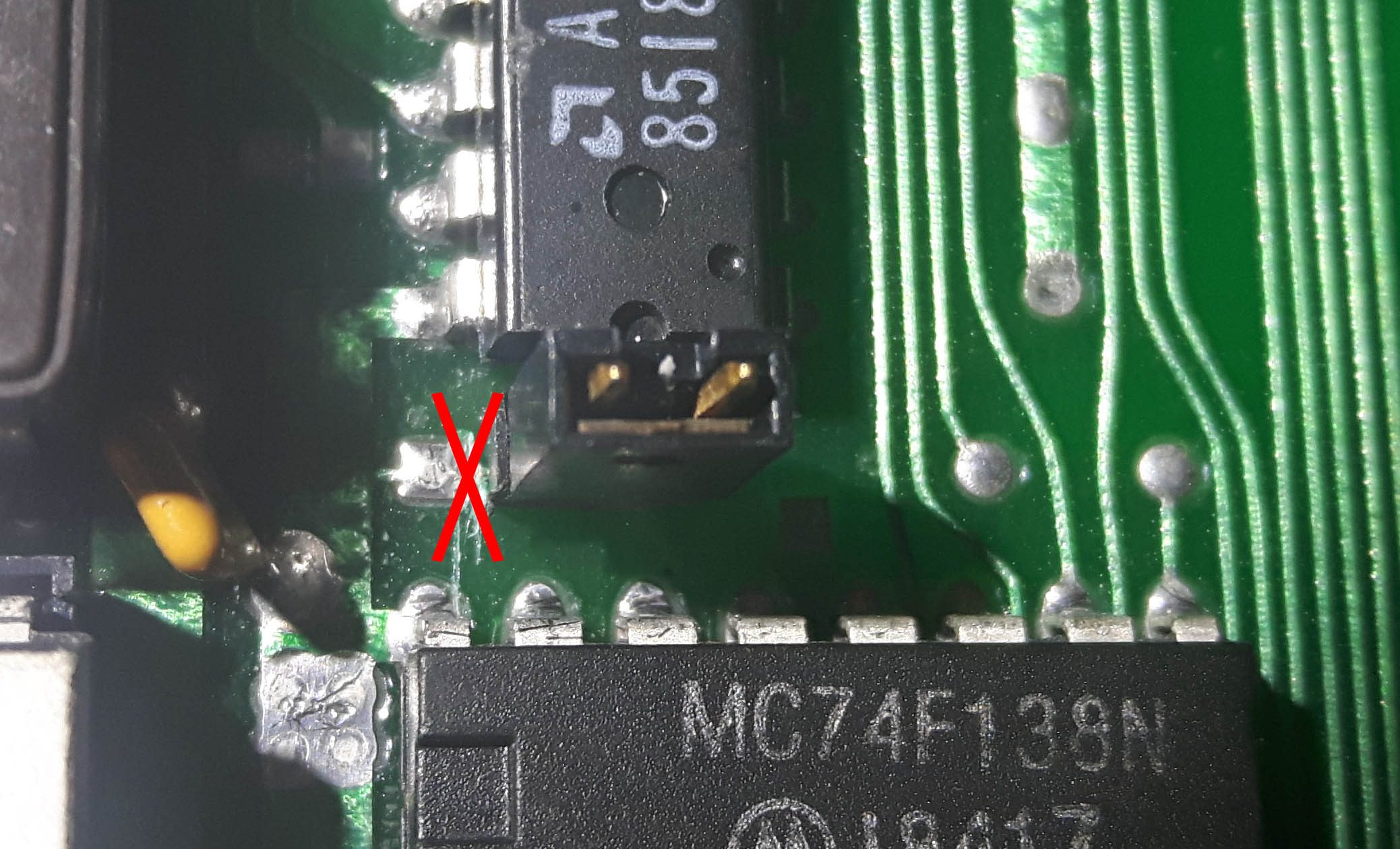
PCB Trace to cut (click to enlarge)
Now, if you want just install 64KBytes EPROMs, losing the ability to install 32KBytes EPROMS, there is nothing else to do but to close the jumper (like you can see in the right photo).
If you want to keep the possibility to install both 32k and 64kBytes EPROM, you must add a resistor on the bottom side of the microprocessor board.
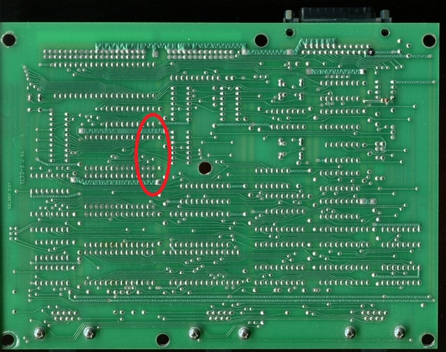
Location of the resistor (not mounted, here)
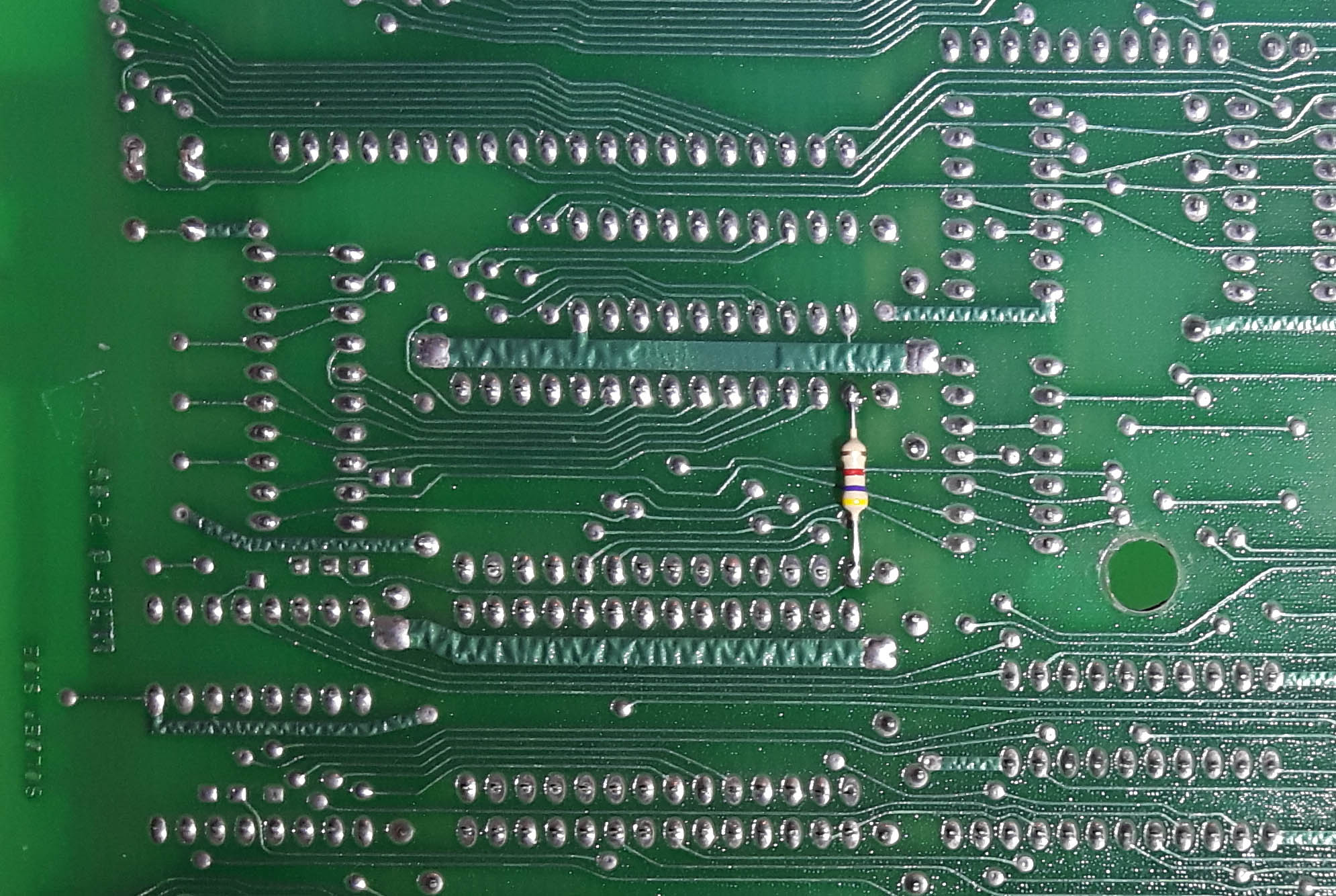
The resistor installed (click to enlarge)
I’ve used a 4.7kOhm 5% resistor (colors are yellow, violet, red, gold) but any value from 2.2kOhm to 10kOhm should work.
With the resistor mounted on the PCB you can use 64KBytes EPROM by installing the jumper and 32KBytes EPROM by removing the jumper.
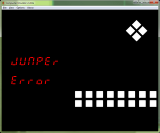
Leaving the jumper installed with a 32KBytes EPROM may or may not work (it depends on the EPROM installed: some work, some don’t) but it should not cause any damage. Not installing the jumper with a 64kBytes EPROM will cause a “Jumper error” display in the firmware.
Closing the jumper without having cut the PCB trace does not work and may damage the Compustar if left on for some time.
A final note: use 64kBytes firmwares on 64kBytes EPROMs (27C512) and 32kBytes firmwares on 32kBytes EPROMs (27C256). If you know how to do it, you can install 32kBytes firmwares on 64kBytes EPROMs, but don’t ask if you don’t: it’s pointless anyway. The other way around (installing 64kBytes firmwares on a 32kBytes EPROM) just does not work.
The ASCOM support protocol uses a RS232 line to enter PC Mode (DTR on the PC side, pin 4 of CN6 on the Compustar, connected to P1.6 of the Compustar microprocessor via a RS232-level converter).
Using a line instead of a simple command on the serial port has several advantages. For example, testing for PC mode in the (constrained) Compustar firmware is way easier than checking for some RS232 command; this check can be done basically everywhere and therefore you don’t have to enter some specific Compustar menu and the Compustar can easily terminate PC mode if the cable is disconnected.
Unfortunately, a quirk in the Compustar hardware makes this detection (cable disconnection in particular) non fully reliable: there is a polarizing resistor (R13 on the Microprocessor board in my schematic reference) which goes against the biasing resistor built into IC31. Therefore, when nothing is actively driving this input, the output value (of IC31) depends on component tolerances (and temperature, probably).
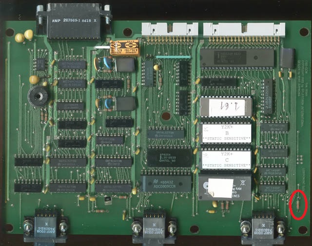
The R13 resistor to remove (click to enlarge)
The fix is quite easy: just remove R13. You may desolder it or even cut it away with a cutter.
This modification has no impact neither on the original firmware nor on non ASCOM-enabled firmwares because all these firmwares don’t use this part of the RS232 circuitry.